

Ultimate Guide to the 300-110 - Latest Sep 11, 2026 Edition Available Now
2026 Updated Verified Pass 300-110 Exam - Real Questions and Answers
NEW QUESTION # 17
A network engineer must design a new Cisco wireless solution that contains three Cisco 9800-40 WLCs.
WLC1 and WLC2 will be combined into one logical unit with SSO and a backup WLC named WLC3 will be joined by using a mobility tunnel. Link redundancy between the WLCs and the switches is required. Which WLCs must the design provide connectivity to the network equipment for LAG to be effective in an SSO failover scenario?
- A. WLC1
- B. WLC2
- C. WLC1 and WLC2
- D. WLC1, WLC2, and WLC3
Answer: C
Explanation:
In a Cisco Catalyst 9800 SSO deployment using Link Aggregation Group (LAG) for network interface redundancy, the SSO pair - WLC1 (active) and WLC2 (standby) - must both have their physical interfaces connected to the network infrastructure as part of the LAG bundle. LAG on the 9800 in an SSO configuration is implemented as a multi-chassis LAG across both the active and standby controllers. This means both WLC1 and WLC2 contribute physical member links to the port channel, and the connected switches must have LACP or PAgP bundle members from both controllers in the same port channel group. When an SSO failover occurs - WLC1 fails and WLC2 takes over as active - the LAG remains operational because WLC2 ' s physical links are already established members of the bundle and continue forwarding traffic without any link renegotiation. If only WLC1 had LAG connectivity and WLC2 had independent links, an SSO failover would cause a LAG topology change requiring re-convergence, introducing downtime. WLC3 is a separate N+1 backup controller joined via a mobility tunnel - not part of the SSO pair and its LAG configuration is independent. Reference: WLSD Study Guide - Catalyst 9800 SSO with LAG, Multi-Chassis Link Aggregation, High Availability Network Redundancy Design.
NEW QUESTION # 18
An engineer must identify the network requirements for a company that has a main office and 10 branch offices. The network must be able to support data, voice, video, and location tracking. Which two factors must be considered? (Choose two.)
- A. number of wireless devices that require access
- B. type of site for which the survey will be performed
- C. security policy of the company for building access
- D. available power sockets in the IT room
- E. business type of the company
Answer: A,B
Explanation:
When designing a wireless network to support diverse services - including data, voice, video, and location tracking - across a distributed enterprise with a main office and 10 branch locations, the two primary design factors directly shaping the RF and capacity architecture are the number of wireless devices requiring access and the type of site where the survey will be performed. The device count (Option B) drives AP density, channel reuse planning, capacity modeling, and controller licensing requirements. Each service type - particularly VoWLAN and video - imposes strict per-client throughput and latency constraints that must be multiplied across the concurrent device population. The type of site (Option C) determines the survey approach, attenuation characteristics, coverage requirements, and antenna selection. A warehouse, hospital, or open-plan office each demands a fundamentally different RF design. Options A and D are organizational considerations, not technical RF design inputs. Option E (power sockets) is an installation logistics concern, not a wireless design factor. Reference: WLSD Study Guide - Requirements Gathering, Site Survey Planning, Capacity and Coverage Design Methodology.
NEW QUESTION # 19
An engineer is estimating the loss between two floors of an office building. Using Ekahau, they have measured -45 dBm at the ground level of the floor with the access point and -50 dBm at the ceiling level of the floor below it. Which value is the loss of the floor?
- A. 5 dB
- B. -95 dB
- C. 95 dB
- D. -5 dB
Answer: A
Explanation:
Floor loss calculation is a fundamental skill in multi-floor wireless site survey methodology. The floor attenuation value represents the signal power reduction caused by penetrating through a single floor structure including the floor decking, subfloor, ceiling material, plenum space, and any structural elements. In this measurement scenario, the engineer has two data points: -45 dBm measured at the ground level of the floor containing the access point (the signal level just below the AP ' s floor) and -50 dBm measured at the ceiling level of the floor below (the signal level just after passing through the floor structure). The floor loss is simply the difference between these two measurements: (-45 dBm) - (-50 dBm) = -45 + 50 = 5 dB. The result is expressed as a positive value (5 dB) representing attenuation - signal power decreases by 5 dB when passing through the floor. Expressing it as -5 dB (Option B) would incorrectly imply a signal gain. The 95 dB values (Options A and D) result from incorrectly adding rather than subtracting the dBm values - a common error when working with negative dBm figures. This floor attenuation value (5 dB) would then be entered into Ekahau ' s floor material properties to improve predictive model accuracy. Reference: WLSD Study Guide - Multi-Floor Signal Propagation, Floor Attenuation Factor (FAF), Ekahau Floor Loss Measurement Methodology.
NEW QUESTION # 20
A community bank has three campus locations and one HQ with the data center. Each campus has four Cisco Catalyst 9120 APs. Poor WAN uplinks cause impacted connectivity back to HQ, and each campus is planned to have its own EWC controller based on C9120 AP to keep traffic local. Guest WLAN will be routed locally.
Employee WLAN must be authenticated 802.1x PEAP via HQ ISE but can pass traffic locally once authenticated. HQ WLC will be the primary backup WLC for each WLC. Which design approach should the consulting engineer take?
- A. One C9120 campus AP must be converted to EWC mode, and the preferred controller is set to that AP with HQ WLC paired as mobility peer and configured as N+1 backup. The campus guest WLAN will use local web auth on guest VLAN. The campus employee WLAN will need the guest anchor back to the HQ employee WLAN.
- B. One C9120 AP in each campus must be converted to EWC mode, and the preferred controller is set to that AP with HQ WLC set as N+1 backup. The campus guest WLAN will use local web auth on guest VLAN, and employee WLAN will need the HQ AAA server to be added to EWC.
- C. Two C9120 campus APs must be converted to EWC mode, one for the active controller and the other for standby with HQ WLC as N+1 backup. The campus guest WLAN will use the guest anchor to HQ WLC for guest VLAN access, and employee WLAN will need the HQ AAA server added to EWC.
- D. Two C9120 campus APs must be converted to EWC mode, one for the active controller and the other for standby set as N+1 backup. The campus guest WLAN will use local web auth on guest VLAN, and employee WLAN will need the HQ AAA server added to EWC.
Answer: B
Explanation:
This community bank design scenario requires precise alignment of EWC deployment scale, AAA integration, and traffic routing decisions with the stated constraints. With four APs per campus and a goal of local traffic handling, converting a single C9120 to EWC mode is optimal - converting two APs to EWC (Options B and C) on a four-AP campus wastes 50% of campus AP infrastructure for controller functions rather than client service. The single EWC AP serves as the active local controller for the remaining three client-serving APs. The HQ WLC set as N+1 backup ensures that if the branch EWC fails, the remaining APs fall back to the centralized controller. For the guest WLAN, local web authentication on the guest VLAN provides the locally routed guest access requirement without requiring WAN connectivity to HQ. For the employee WLAN, adding the HQ ISE AAA server to the EWC ' s RADIUS configuration enables 802.1x PEAP authentication to traverse the WAN to ISE at the time of client association. Once authenticated, traffic is locally switched - satisfying both the central authentication and local traffic routing requirements simultaneously. Option D ' s use of guest anchor for the employee WLAN is architecturally incorrect and would route traffic through HQ rather than locally. Reference: WLSD Study Guide - EWC Design, N+1 Redundancy, AAA Integration for Branch WLANs, Local Web Authentication.
NEW QUESTION # 21
An engineer is conducting a Layer 2 site survey. Which type of client must the engineer match to the survey?
- A. normal client
- B. best client available
- C. worst client available
- D. phone client
Answer: C
Explanation:
When conducting a Layer 2 site survey, it is recommended to match the survey to the worst client available.
This ensures that the wireless network is designed to provide adequate coverage and performance even for clients with the poorest RF capabilities, thereby providing a consistent user experience for all devices. The worst client typically has fewer antennas, lower receiver sensitivity, and less sophisticated chipsets. By designing to its limitations, the engineer guarantees that every device in the environment meets the minimum performance threshold. Using the best client (Option A) or an average client (Option C) would result in coverage gaps for less capable devices. A phone client (Option B) may have unique characteristics but is not a universally applicable standard for general survey purposes. Reference: WLSD Study Guide - Site Survey Methodology, Client Selection for Survey, Layer 2 Pre-Deployment Survey.
NEW QUESTION # 22
A customer requires the wireless network to perform real-time analysis to reduce congestion, link usage, and infrastructure upgrades. Which Cisco technology can accomplish this analysis?
- A. Application Visibility and Control
- B. band selection
- C. 802.11r
- D. QoS
Answer: A
Explanation:
Cisco Application Visibility and Control (AVC) is a deep packet inspection and traffic classification framework integrated into the Cisco WLC and AP platform. AVC performs real-time analysis of wireless client traffic, classifying applications based on Layer 4-7 signatures using the NBAR2 (Network Based Application Recognition) engine. This provides the network administrator with granular visibility into exactly which applications are consuming bandwidth - enabling data-driven decisions about network congestion remediation, link utilization management, and infrastructure investment planning. For example, AVC can reveal that a video streaming application is consuming 60% of available wireless bandwidth during peak hours, informing the decision to implement QoS rate limiting for that application class or upgrade the backhaul infrastructure. AVC also supports control functions through per-application QoS policies, rate limiting, and traffic shaping - directly addressing congestion reduction. Band selection (Option A) steers dual-band clients to 5 GHz but provides no application-level analysis. QoS (Option B) implements traffic prioritization but requires prior application identification - it does not perform the analysis itself. 802.11r (Option D) is a fast roaming protocol with no relevance to traffic analysis or congestion management.
Reference: WLSD Study Guide - Application Visibility and Control, NBAR2 Integration, Wireless Traffic Analysis and Management.
NEW QUESTION # 23
An enterprise network is deploying two Cisco Catalyst 9800 WLCs in a data center to ensure uninterrupted wireless services for a campus with thousands of users. The IT management requests a design that enables seamless failover without client reauthentication or loss of connectivity if one controller fails. Ease of configuration and ongoing management are high priorities. The controllers will be connected via a high-speed LAN segment, and both must support full active-passive redundancy for all managed APs. Which design approach meets the requirements?
- A. Enable N+1 redundancy, assigning primary and secondary controllers to each AP, and use DHCP for failover.
- B. Implement SSO with redundancy management interface and AP SSO enabled between the two controllers.
- C. Configure the 9800 WLCs in separate mobility groups and synchronize configurations manually.
- D. Deploy the controllers with VRRP to provide gateway redundancy and manually synchronize WLAN profiles.
Answer: B
Explanation:
Cisco Stateful Switchover (SSO) on the Catalyst 9800 platform is the definitive high availability solution when requirements specify zero client reauthentication during failover, active-passive redundancy, and ease of management. With SSO enabled, the active and standby 9800 WLCs maintain a synchronized state database via a dedicated redundancy link - this includes all client association state, authentication credentials, AP join information, and WLAN configurations. When the active controller fails, the standby assumes control instantaneously with no CAPWAP session teardown and no 802.1X reauthentication required. The Redundancy Management Interface (RMI) provides a dedicated in-band keepalive and state synchronization path. N+1 redundancy (Option D) requires APs to rejoin a new controller and clients to reauthenticate, failing the seamless requirement. Manual configuration synchronization (Options A and C) is operationally complex and does not guarantee stateful failover. VRRP provides gateway redundancy at Layer 3 but does not address CAPWAP session continuity. Reference: WLSD Study Guide - Catalyst 9800 High Availability, SSO Architecture, Redundancy Management Interface Configuration.
NEW QUESTION # 24
A wireless engineer must design a WLAN for a university that requires outdoor Wi-Fi access. Which obstruction has the greatest effect on wireless signal propagation?
- A. poles
- B. wind
- C. trees
- D. rain
Answer: C
Explanation:
In outdoor wireless deployments, foliage - particularly dense trees - represents the most significant and variable RF obstruction that engineers must account for during site survey and design. Trees are problematic for multiple compounding reasons: the high water content of living tissue causes signal absorption consistent with the principle that water is an effective absorber of 2.4 GHz and 5 GHz RF energy; the irregular branching structure causes multi-path scattering; and foliage density changes seasonally, meaning signal propagation characteristics measured during winter may differ substantially from summer readings when leaves are fully developed. A fully leafed deciduous tree can attenuate a 5 GHz signal by 6-15 dB depending on density and depth. Wind (Option A) causes only momentary mechanical movement of foliage and is not an obstruction itself. Rain (Option B) causes some absorption at higher frequencies but its effect at 2.4 GHz and
5 GHz in typical conditions is marginal compared to foliage. Poles (Option D) are thin structures with minimal RF impact. Outdoor surveys for university campuses must specifically account for tree locations, canopy density, and seasonal variation. Reference: WLSD Study Guide - Outdoor Wireless Design, Environmental RF Attenuation Factors, Outdoor Site Survey Considerations.
NEW QUESTION # 25
An enterprise is using two wireless controllers to support the wireless network. The data centre is located in the head office. Each controller has a corporate WLAN configured with different SSID names. The APs are installed using a round-robin approach to load balance the traffic. What should be changed in the configuration to optimize roaming?
- A. Move all access points to one controller and use the other as N+1 HA.
- B. Use the same WLAN name for the corporate network on both controllers.
- C. Use the same WLAN name for the corporate network on both controllers.
- D. Place the access points per floor on the same controller.
Answer: B
Explanation:
To optimize roaming in a wireless network with multiple controllers, it is essential to use the same WLAN name (SSID) across all controllers. When SSIDs differ between controllers, clients perceive them as different networks and must perform a full re-association and re-authentication when roaming between APs managed by different controllers. This causes a roaming disruption equivalent to connecting to an entirely new network. By using identical SSID names on both controllers, clients can seamlessly roam between APs on different controllers within the same mobility group - the controllers exchange client state information via the mobility tunnel, enabling seamless handoff. In the scenario described, ' Copr-NET390595865WLC-1 ' and
' Copr-NET6837l638WLC-2 ' are different SSIDs, meaning clients cannot roam transparently between them.
Making both controllers broadcast the same SSID name (and using a mobility group to connect the controllers) resolves this. Reference: WLSD Study Guide - SSID Consistency Across Controllers, Inter- Controller Roaming, Mobility Group Configuration.
NEW QUESTION # 26
A company is upgrading its wireless infrastructure and is in a state of transition. Some parts of the company ' s building still run on the legacy WLC. The new WLC is not located at the same site as the legacy WLC. The company requires seamless client inter-controller roaming between the new WLC and the legacy WLC, with no disruptions. Both WLCs are separated by firewalls. Which troubleshooting command validates that the mobility control packets between the WLCs can be sent and received?
- A. mapping mobility_peer_management IP address
- B. mapping mobility_peer IP address
- C. debug mobility config enable
- D. debug mobility handoff enable
Answer: D
Explanation:
The command ' debug mobility handoff enable ' is used to validate the mobility control packets between Wireless LAN Controllers (WLCs). This command enables debugging of the handoff process, which is critical for ensuring seamless client roaming between controllers. When WLCs are separated by firewalls, it is essential to confirm that mobility control packets can traverse these firewalls without being dropped or rejected. The ' debug mobility handoff enable ' command allows network administrators to monitor the handoff process in real time and identify whether mobility PDUs are being exchanged successfully. If mobility control packets are being blocked by the firewall, this debug output will show failures in the handoff sequence. This command directly validates bidirectional mobility traffic flow, making it the correct troubleshooting tool for the scenario described. Options A and D are not valid Cisco WLC commands. Option C enables configuration-level mobility debugging but does not specifically validate handoff packet flow.
Reference: WLSD Study Guide - Mobility Troubleshooting, Debug Commands, Inter-Controller Roaming Validation.
NEW QUESTION # 27
An engineer is designing a wireless solution for a corporate campus which includes two primary buildings:
Research and Operations. The design must ensure seamless mobility for employees moving between buildings, support uninterrupted connectivity for real-time applications, and facilitate efficient Layer 2 and Layer 3 roaming. Each building ' s 9800-80 WLC manages its local APs, and the solution must support 802.11 r/k/v while maintaining an effective mobility control plane. Which design approach leverages Cisco mobility group architecture to meet the requirements?
- A. Add both 9800-80 WLCs in a single mobility group with no specific roles assigned, enabling peer-to- peer coordination for seamless roaming across buildings.
- B. Designate the Research building ' s WLC as the primary controller and the Operations building ' s WLC as a secondary controller within a single mobility group to centralize mobility management.
- C. Assign each 9800-80 WLC to separate mobility groups, one for each building, to isolate traffic and mitigate the risk of overloading a single mobility group.
- D. Establish the Operations building ' s WLC as an anchor controller, configuring the Research building ' s WLC to tunnel all client traffic to it for centralized traffic management.
Answer: A
Explanation:
Cisco ' s mobility group architecture enables seamless client roaming between WLCs by establishing a trusted peer relationship and shared mobility domain. When two Cisco Catalyst 9800-80 WLCs are placed in the same mobility group, they establish CAPWAP mobility tunnels enabling both Layer 2 and Layer 3 roaming with session continuity including IP address preservation. Within the same mobility group, WLCs exchange client state information, allowing 802.11r Fast BSS Transition, 802.11k neighbor reports, and 802.11v BSS Transition Management to function across controller boundaries. No specific primary or secondary roles are assigned within a mobility group - all members are peers with equal standing for roaming purposes, which is precisely what Option D describes. Option A incorrectly implies a hierarchical structure that does not exist in mobility group peer relationships. Option B separating the WLCs into different groups would break inter- building roaming since clients would experience a full re-authentication cycle. Option C imposing an anchor relationship is appropriate only for guest WLANs. Reference: WLSD Study Guide - Mobility Group Architecture, Inter-Controller Roaming, 802.11r/k/v Fast Roaming Design.
NEW QUESTION # 28
An engineer is designing a solution where guests terminate on an anchor controller in the DMZ. The engineer is having issues and wants to test connectivity between members of a mobility group. Which two steps must be performed to test whether a mobility control packet can be reached over the management interface?
(Choose two.)
- A. Use the tracert command on the WLC.
- B. Use the mping command on both WLCs.
- C. Use the eping command on both WLCs.
- D. Open UDP port 16666 between both WLCs.
- E. Open IP protocol 97 between both WLCs.
Answer: B,D
Explanation:
To test whether mobility control packets can reach between WLC peers in a mobility group (used to validate the anchor controller DMZ setup), two steps are required. First, the mping (mobility ping) command (Option A) is the Cisco WLC CLI tool specifically designed to test mobility control path connectivity between WLC peers. Running mping on both WLCs verifies that mobility control messages (UDP port 16666) can be exchanged bidirectionally. Second, UDP port 16666 must be open between the WLCs (Option C) - mping uses this port, and if it is blocked by a firewall (which is common when the anchor is in a DMZ), the mobility control path cannot be established. These two steps together - sending mping packets and confirming the firewall permits UDP 16666 - validate mobility control plane connectivity. The eping (EoIP ping) command (Option B) tests the data path tunnel, not the control path. IP Protocol 97 (Option D) is for the data plane in legacy mobility mode. Tracert (Option E) traces routing paths but does not validate mobility protocol connectivity. Reference: WLSD Study Guide - Mobility Group Troubleshooting, mping Command, UDP
16666 Firewall Requirements.
NEW QUESTION # 29
In a FlexConnect deployment, which role does the site tag play?
- A. It assigns IP addresses to wireless clients for the site APs.
- B. It configures the switch port settings for FlexConnect APs.
- C. It manages the firewall policies for the site APs.
- D. It defines the roaming domain for FlexConnect APs.
Answer: D
Explanation:
In the Cisco Catalyst 9800 IOS XE WLC configuration framework, the site tag serves as the primary organizational and functional grouping element for FlexConnect APs at a given physical location. The site tag defines the FlexConnect site - a logical boundary within which APs can perform local switching and local inter-AP roaming without requiring CAPWAP tunnel traversal to the WLC for every client handoff. Within a FlexConnect site defined by the site tag, APs can exchange client roaming context information directly with each other (peer-to-peer), enabling fast Layer 2 roaming for clients moving between APs that share the same site tag - effectively defining the roaming domain for FlexConnect APs at that site. The site tag also references the flex profile (which defines VLAN mappings, local auth settings, and split tunneling parameters) and the AP join profile. Switch port configuration (Option A) is performed on the infrastructure switches, not through the WLC site tag. IP address assignment (Option B) is a DHCP function. Firewall policies (Option C) are applied through ACLs and policy tags, not site tags. Reference: WLSD Study Guide
- Catalyst 9800 Tag Architecture, FlexConnect Site Tag Role, Local Roaming in FlexConnect Deployments.
NEW QUESTION # 30
Refer to the exhibit. A network engineer is designing a high availability SSO on a Cisco Catalyst 9800-40 WLC with multi-LAG network redundancy on two Catalyst 9300 switches. The LAG requirements are: * Each LAG must be connected to a single switch. * Different VLANs must be assigned to different LAGs. * The controller must learn the identity of partners that can support LAG capabilities in each port. * When any active LAG ports fail, a standby LAG port must provide redundancy. Which protocol must be used for the port channel on the interface to meet the design requirements?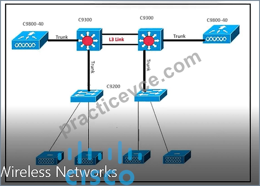
- A. LACP
- B. PAgP
- C. OSPF
- D. BGP
Answer: A
Explanation:
The design requirements specify a multi-LAG configuration where each LAG connects to a single switch, different VLANs are assigned to different LAGs, the controller must dynamically learn partner LAG capabilities per port, and standby ports provide redundancy upon active port failure. These requirements collectively point to IEEE 802.3ad LACP (Link Aggregation Control Protocol) as the correct protocol. LACP is the industry-standard IEEE protocol that enables dynamic negotiation of LAG membership between endpoints - the WLC and each Catalyst 9300 switch exchange LACP PDUs (LACPDUs) to discover port capabilities, negotiate bundle membership, and monitor link status. LACP supports active and passive port states where active ports initiate negotiation and passive ports respond, and it provides the standby port mechanism through its hot-standby capability for link redundancy within the bundle. The requirement to ' learn the identity of partners that can support LAG capabilities ' is the defining characteristic of LACP ' s standardized PDU exchange mechanism. PAgP (Option C) is a Cisco proprietary port aggregation protocol that, while functionally similar, is not the IEEE standard and is incompatible with non-Cisco equipment in mixed environments. OSPF (Option B) and BGP (Option D) are Layer 3 routing protocols entirely unrelated to port channel negotiation. Reference: WLSD Study Guide - Catalyst 9800 LAG Configuration, LACP IEEE 802.3ad, Multi-LAG High Availability Design.
NEW QUESTION # 31
An engineer must assess an existing company WLAN to determine the possibility for future IEEE 802.11ac Wave 2 wireless deployment. All access switches are Fast Ethernet-capable only, and the wired infrastructure between existing APs and access switches is based on the CAT 6A standard. Which two actions provide maximum support of Cisco 3800 Series access points? (Choose two.)
- A. Ensure that cable distances between access switches and APs are not longer than 100 meters.
- B. Replace the existing wiring infrastructure with the CAT-7E wiring standard.
- C. Replace the existing switches with gigabit switches with 10G uplinks.
- D. Replace the existing switches with mGig switches.
- E. Ensure that cable distances between access switches and APs are not longer than 55 meters.
Answer: C,D
Explanation:
Cisco 3800 Series APs support IEEE 802.11ac Wave 2, which can deliver throughput exceeding 1 Gbps. Fast Ethernet switches are limited to 100 Mbps per port, creating a severe bottleneck. The two actions that provide maximum support are replacing with mGig switches (Option A) and replacing with gigabit switches with 10G uplinks (Option B). mGig (Multi-Gigabit Ethernet) switches support 2.5G and 5G speeds over existing CAT
6A cabling, allowing the full throughput of 802.11ac Wave 2 APs to be utilized without replacing the existing cable plant. Gigabit switches with 10G uplinks ensure that the access layer can support 1 Gbps per AP port while providing sufficient uplink capacity. Since the existing cabling is already CAT 6A, which supports 10 Gbps over short distances and 5 Gbps over 100 meters, there is no need to replace the wiring (Option D eliminates). The 100-meter distance limitation (Option C) already applies to standard Ethernet and is met by CAT 6A - this is not an action but a constraint check. Option E (55 meters) is only relevant for specific
5GBASE-T configurations and doesn ' t maximize support compared to A and B. Reference: WLSD Study Guide - mGig Infrastructure, 802.11ac Wave 2 Infrastructure Design, Switch Upgrade Planning.
NEW QUESTION # 32
A consulting engineer is preparing to survey a brownfield deployment for a 6000-sqft building with four floors that have APs. The entire building is being remodeled and the furniture, office walls, and decoration are being updated. The engineer must perform a survey analysis on the potential RF impact of newer furniture materials. How must the survey be conducted?
- A. Evaluate the neighbor APs strength and density based on the radio statistics information of each AP.
- B. Use a survey tool with the existing AP positions using building floor maps and material configuration.
- C. Perform a sweep analysis first to predict the signal strength across each point in a floor.
- D. Measure upstream and downstream data rates based on the remodeling of the building.
Answer: B
Explanation:
A brownfield deployment scenario involves an existing operational wireless network where a physical remodel will change the RF environment. The engineer ' s task is to assess the impact of new furniture and wall materials on the existing AP placement - a scenario requiring a predictive re-analysis of how changed materials will alter propagation from the existing AP locations. Using a survey tool such as Ekahau with the known AP positions superimposed on updated floor plans, the engineer can reconfigure material attenuation properties to reflect new construction materials and re-run the predictive propagation model. This produces a before/after comparison identifying coverage gaps or interference hotspots introduced by the remodel without requiring physical downtime or temporary infrastructure changes. Option A (sweep analysis) measures existing signal strength but does not model future material changes. Option B (neighbor AP statistics) evaluates the current RF environment using WLC data, not future conditions. Option C (throughput measurements) tests current performance, not future RF impact. Reference: WLSD Study Guide - Brownfield Survey Methodology, Material Attenuation Modeling, Post-Remodel RF Impact Analysis.
NEW QUESTION # 33
A network engineer is designing a wireless network to support high availability. The network will need to support the total number of APs and client SSO. Live services should continue to work without interruption during the failover. Which two requirements need to be incorporated into the design to meet these needs?
(Choose two.)
- A. WLC 7.5 code or more recent
- B. back-to-back direct connection between WLCs
- C. 10 sec RTT
- D. redundant WLC
- E. controller high availability pair with one of the WLCs having a valid AP count license
Answer: D,E
Explanation:
To support high availability with client SSO (Stateful Switchover) and no interruption to live services during failover, the design must incorporate two requirements. First, redundant WLCs (Option A) are essential - without a physical standby controller, there is no entity to take over when the primary WLC fails. In an SSO configuration, one WLC is active and one is standby, and the standby must be ready to assume the active role instantaneously. Second, the high availability pair requires one of the WLCs to have a valid AP count license (Option B). In a Cisco WLC SSO pair, the standby controller ' s AP count license applies when it becomes active - without a valid license on at least one WLC in the pair, APs cannot join after failover. A 10-second RTT maximum (Option C) is a latency requirement for the redundancy link but is not a primary design requirement that addresses the overall high availability architecture. A back-to-back direct connection (Option D) is one way to connect the redundancy ports but is not mandatory if a low-latency switch connection is used. Code version 7.5 or newer (Option E) is a requirement for specific legacy SSO platforms but not a general design principle. Reference: WLSD Study Guide - WLC SSO High Availability Design, AP License Requirements, Redundant Controller Architecture.
NEW QUESTION # 34
A network engineer must design a new wireless solution for a company, but the budget can only stretch to include a single Cisco 9800-40 WLC. The company requires high availability between the WLC and the core switch in the event of a cable failure. The WLC must dynamically manage port redundancy and perform load balancing between APs transparently. Which design approach must the engineer take to meet the requirements?
- A. LAG
- B. PAgP
- C. LACP
- D. Multi-LAG
Answer: A
Explanation:
Link Aggregation Group (LAG) is the correct design approach for a single Cisco 9800-40 WLC that requires high availability between the WLC and the core switch in the event of a cable failure. LAG combines multiple physical ports on the WLC into a single logical channel, providing both redundancy (traffic automatically redistributes across remaining links when one fails) and load balancing (traffic is distributed across all active links). Importantly, LAG operates transparently to AP management - APs see a single logical uplink regardless of which physical port their traffic traverses. With a single WLC, Multi-LAG (Option B) is not applicable - Multi-LAG is a feature of the Catalyst 9800 that allows multiple separate LAG bundles for different network connections, typically used with SSO pairs. LACP (Option C) is the protocol used to negotiate LAG member links - it is the mechanism within LAG, not an independent design approach. PAgP (Option D) is a Cisco proprietary alternative to LACP for port aggregation but the question asks for the design approach, which is LAG. Reference: WLSD Study Guide - Catalyst 9800 LAG Design, Port Redundancy and Load Balancing, Single-Controller High Availability.
NEW QUESTION # 35
An engineer must design AP placements for a new branch office that contains two floors. The engineer uses Ekahau to complete the predictive survey. To calculate the signal bleed through between floors, the engineer creates a building, adds the floors, and attenuation areas. After the scale is set, what else must be added on the floors to accurately measure the signal bleed at a specific location?
- A. Choose the access point models.
- B. Draw in coverage areas.
- C. Start the auto planner.
- D. Add alignment points.
Answer: D
Explanation:
In Ekahau Site Survey ' s multi-floor predictive modeling workflow, alignment points are the critical mechanism that allows the software to understand the precise vertical spatial relationship between floors in a multi-story building. Once floor plans are imported with their scale correctly defined, alignment points must be placed on each floor at the same real-world physical location - such as a stairwell corner, elevator shaft, or structural column - so that Ekahau can accurately calculate vertical signal propagation and inter-floor RF bleed. Without alignment points, the software has no spatial reference to determine which area on Floor 2 is directly above a given point on Floor 1, making floor-to-floor signal bleed calculations geometrically impossible. Drawing coverage areas (Option A) is a post-AP-placement activity. Starting the auto planner (Option B) would attempt to place APs without the required spatial reference. Choosing AP models (Option D) is a subsequent step. Alignment points are a fundamental requirement for any predictive survey involving multi-floor buildings. Reference: WLSD Study Guide - Ekahau Predictive Survey Methodology, Multi- Floor Building Configuration, Signal Propagation Modeling.
NEW QUESTION # 36
A retail customer opened two new branch locations, and the main store HQ handles data center operations.
Each branch location has three Cisco Catalyst 9130 APs. The data center has a Catalyst 9800 WLC with 18 Catalyst 9130 APs. Growing business and poor WAN uplinks cause impacted branch AP and wireless client connectivity back to HQ, and each branch location is now planned to have its own EWC controller based on C9130 AP to keep traffic local. This new design must accommodate: guests and employees sharing the same WLAN with different VLANs, guest uplink and downlink traffic restricted to 2 Mbps, and each branch acting as secondary or tertiary backup to another branch with the data center WLC always being the primary. Which design approach should the consulting engineer take?
- A. Two C9130 branch APs must be converted to EWC mode, one for the active controller and the other for standby, with the standby EWC set as N+1 backup. HQ AAA must be added to EWC, and WLAN with dot1x + AAA override must be configured.
- B. Two C9130 branch APs must be converted to EWC mode, one for the active controller and the other for standby, with HQ WLC set as a primary N+1 backup, and other branches ' EWC must be added as mobility peers. The branch WLAN will use the guest anchor to HQ WLC for guest VLAN access.
- C. One C9130 branch AP must be converted to EWC mode, and the preferred controller is set to that AP with HQ WLC set as a primary N+1 backup and other branches ' EWC AP as secondary and tertiary.
HQ AAA must be added to EWC, and WLAN with MAB + AAA override must be configured. - D. One C9130 branch AP must be converted to EWC mode, and the preferred controller is set to that AP with HQ WLC set as N+1 backup. The branch guest WLAN will use local web auth on guest VLAN.
Answer: C
Explanation:
This multi-constraint design scenario requires precise alignment of EWC architecture, N+1 redundancy hierarchy, AAA integration, and WLAN security policies. Option B correctly addresses all requirements.
With only three APs per branch and a requirement to keep traffic local, converting a single C9130 to EWC mode is the correct and resource-efficient approach - converting two APs to EWC (Options A and C) wastes AP capacity in a small three-AP branch. The preferred controller set to the EWC AP ensures local APs join locally. The HQ WLC as primary N+1 backup satisfies the data center WLC always being primary requirement. Other branches ' EWC APs configured as secondary and tertiary controllers creates the cross- branch redundancy hierarchy. Since guests and employees share the same SSID but require different VLANs, MAC Authentication Bypass (MAB) with AAA override allows the HQ ISE/AAA server to return VLAN attributes based on device or user identity - dynamically assigning the correct VLAN at the policy level. The
2 Mbps guest rate limiting is applied through per-client QoS policies on the EWC. Option D ' s use of local web auth for guests does not enable dynamic VLAN assignment from AAA. Reference: WLSD Study Guide
- EWC Architecture, N+1 Redundancy Hierarchy, AAA Override and Dynamic VLAN Assignment.
NEW QUESTION # 37
What causes the most signal attenuation based on the wireless design tools?
- A. office window
- B. cinder block wall
- C. glass wall
- D. metal door
Answer: D
Explanation:
Metal doors cause the most signal attenuation among common building materials due to the fundamental electromagnetic properties of metal. Metal is highly reflective and absorptive of radio frequency signals - it creates what is effectively a Faraday cage effect around any room or space it encloses. In wireless design attenuation modeling tools such as Ekahau, metal is assigned the highest attenuation value among standard building materials, typically 30+ dB per surface. Cinder block walls (Option A) are dense and provide significant attenuation (10-15 dB) but are not as RF-impenetrable as solid metal. Glass walls (Option C) and office windows (Option D) have relatively low attenuation values (2-4 dB) due to the minimal RF-absorbing properties of glass. When engineers model attenuation materials in predictive survey tools, metal doors and metal-containing structures consistently produce the highest per-surface attenuation values, making them the primary barrier obstacles to plan around. Reference: WLSD Study Guide - RF Signal Attenuation, Building Material Attenuation Values, Predictive Survey Material Modeling.
NEW QUESTION # 38
A hospital has a Cisco Catalyst 9800 Series Wireless Controller in an SSO solution deployed in the primary data center. The hospital plans to increase redundancy in the wireless environment. Management decides to deploy an extra Catalyst 9800 WLC offsite to another data center on a different subnet. A WAN link connects the data centers with a firewall at both ends. Which two design approaches must the engineer take to ensure that the APs can fail over? (Choose two.)
- A. Open UDP ports 16666 and 16667 between the wireless controllers.
- B. Create a mobility tunnel between the wireless controllers.
- C. Open HTTPS port 443 between the wireless controllers.
- D. Create a mobility group with the same names on both wireless controllers.
- E. Create a static RF group leader on one of the wireless controllers.
Answer: A,B
Explanation:
For APs to be able to fail over between a primary SSO pair in one data center and a standalone WLC in a remote data center connected via WAN with firewalls, two design requirements must be met. First, a mobility tunnel must be created between the wireless controllers (Option A). The mobility tunnel enables the controllers to exchange mobility control messages, peer information, and eventually AP context when failover occurs. Without the mobility tunnel, the remote WLC is not recognized as a valid failover target by the APs through the mobility domain. Second, UDP ports 16666 and 16667 must be open through the firewalls between the controllers (Option D). UDP port 16666 is used for mobility control traffic and UDP port 16667 is used for mobility data traffic - both must be permitted through the firewalls at both data centers for the mobility tunnel to establish and function. HTTPS port 443 (Option B) is used for web management and API communication, not for mobility tunneling. A static RF group leader (Option C) is a RRM configuration unrelated to AP failover capability. Creating a mobility group with the same names (Option E) is a component of the configuration but alone is insufficient without the mobility tunnel and open firewall ports. Reference:
WLSD Study Guide - Inter-Site WLC Failover Design, Mobility Tunnel Requirements, Firewall Port Planning for WAN-Separated Controllers.
NEW QUESTION # 39
An engineer is performing an AP-on-a-stick survey and finds that the 5 GHz channel overlap is too high when an appropriate number of APs are used for the density requirements. Which two actions during the survey reduce channel overlap? (Choose two.)
- A. Increase AP transmit power to improve the SNR.
- B. Raise the minimum data rate to 24 Mbps.
- C. Use directional antennas to limit the coverage area of some APs.
- D. Enable power saving mode.
- E. Allow the use of UNII-2e channels.
Answer: B,C
Explanation:
Raising the minimum data rate to 24 Mbps reduces the effective coverage range of each AP because clients at the cell edge operating at low data rates are effectively excluded from the cell. This shrinks cell size, reducing channel overlap between neighboring APs on the same channel. Using directional antennas limits the coverage area of some APs by focusing RF energy in specific directions rather than radiating omnidirectionally, which directly reduces the lateral overlap between adjacent APs. Increasing AP transmit power (Option B) would worsen overlap, not reduce it. Allowing UNII-2e channels (Option C) provides more channel options but does not reduce the physical cell overlap - it only provides more channels to avoid co- channel interference. Power saving mode (Option E) is a client-side power management feature unrelated to AP cell sizing during a survey. Reference: WLSD Study Guide - Channel Overlap Mitigation, Data Rate Configuration, Directional Antenna Use Cases.
NEW QUESTION # 40
An educational organization recently deployed an anchored WLAN and has a high number of client connections at any given time that stream video. The wireless infrastructure includes two Cisco 9800 WLCs.
To prevent web traffic being slow, an engineer must configure the deployment to prevent excessive fragmentation of the client data. Which configuration must the engineer apply?
- A. Increase the MTU on both controllers.
- B. Set the MTU on both controllers to match.
- C. Adjust the TCP MSS value below the fragmentation point.
- D. Set the do not fragment bit on the mobility tunnel.
Answer: C
Explanation:
In an anchored WLAN deployment, client traffic is encapsulated within CAPWAP mobility tunnels between the foreign WLC (where the AP joins) and the anchor WLC (in the DMZ or designated network segment).
This tunneling adds encapsulation overhead - CAPWAP/mobility tunnel headers consume a portion of the available MTU on the transport path. When video streaming clients generate large TCP segments, these segments may exceed the effective MTU of the mobility tunnel path, causing IP fragmentation at the WLC or along the path to the anchor. Fragmentation significantly degrades throughput and increases CPU overhead for high-volume video traffic. The correct solution is TCP MSS Clamping - reducing the Maximum Segment Size value advertised in TCP SYN packets so that TCP endpoints negotiate a segment size remaining below the fragmentation threshold. The Cisco 9800 WLC supports TCP MSS adjustment, which intercepts TCP handshake packets and rewrites the MSS option to a value accounting for CAPWAP tunnel overhead. Setting matching MTUs (Option A) does not prevent fragmentation if the effective tunnel MTU is lower than the client segment size. Increasing the MTU (Option B) is often constrained by physical infrastructure. Setting the DF bit (Option D) would cause packets to be dropped rather than fragmented.
Reference: WLSD Study Guide - Anchored WLAN Design, CAPWAP Mobility Tunnel MTU, TCP MSS Clamping.
NEW QUESTION # 41
......
Dumps Moneyack Guarantee - 300-110 Dumps Approved Dumps: https://www.practicevce.com/Cisco/300-110-practice-exam-dumps.html